Understanding Pile Foundation Design

A pile must do two things at once: carry axial load into the ground and resist lateral load by bending against it. This article looks at how both actually behave, and how greenPile analyses them: shaft and base capacity to EN 1997-1, the full non-linear p-y response for lateral action, and a code verified section to EN 1992-1-1 / EN 1993-1-1 for every load combination.
Author: Purandhar Reddy Bommana
Published: August 11, 2026
Featured image: Understanding Pile Foundation Design

Pile foundations carrying load into the ground

A pile transfers load from a structure into deeper, competent ground, and it usually has to do so in two directions at once. Vertically, it carries axial load through friction along its shaft and bearing at its base. Horizontally, it resists lateral load (wind and seismic actions, earth and water pressure, mooring and berthing forces) by bending against the soil around it. Both are soil-structure interaction problems: the ground’s response depends on the pile’s movement, and the pile’s movement depends on the ground’s response.

The designer therefore has to answer two coupled questions: is the pile able to carry the load into the ground (capacity), and does it move, bend and remain adequate under that load (serviceability and section strength)? greenPile answers both, to Eurocode, in a single model: the axial capacity to EN 1997-1, the lateral response by non-linear p-y analysis, and the pile section itself to EN 1992-1-1 or EN 1993-1-1.

Axial capacity: shaft friction and end bearing

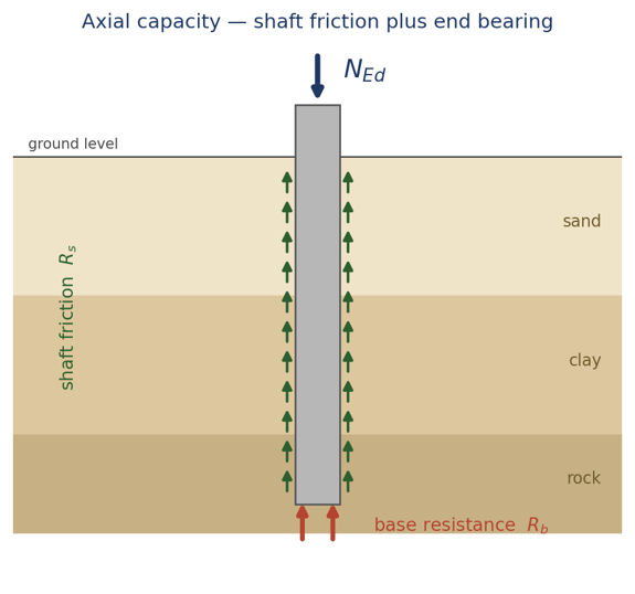
A pile carries axial load in two ways: friction mobilised along its shaft and bearing developed at its base, and greenPile builds both from the ground profile in accordance with EN 1997-1 (Eurocode 7).

Along the shaft, the unit friction is derived from each layer’s character: an effective stress β method in granular soils, an α (adhesion) method in clays, or a Ks·tanδ formulation. Integrated over the embedded length it gives the characteristic shaft resistance. At the base, the unit end bearing follows the appropriate mechanism: Nq·σ′v in sand, Nc·cu in clay, or a rock-strength relation, acting over the base area. The characteristic resistance is the sum of the two:

$$R_{c,k} = \sum_{i} q_{s,i}\,\pi D\,\Delta z_{i} + q_{b}\,\frac{\pi D^{2}}{4}$$
A pile carries axial load through shaft friction (Rs) along its length and end bearing (Rb) at its base
A pile carries axial load through shaft friction (Rs) along its length and end bearing (Rb) at its base.

These characteristic resistances are then reduced to a design resistance. greenPile applies the Eurocode 7 partial factors for the selected Design Approach (DA1, DA2 or DA3), factoring the resistance, or the soil strength, as that approach requires, together with any model factor:

$$R_{c,d} = \frac{R_{s,k}}{\gamma_{s}\,\gamma_{Rd}} + \frac{R_{b,k}}{\gamma_{b}\,\gamma_{Rd}}$$

The water table is tracked through the profile, so that effective stresses, and hence both shaft friction and end bearing, use buoyant unit weights below it. A serviceability estimate of settlement is reported against the usual 10%·D criterion, and downdrag (negative skin friction), where it occurs, is treated as a permanent action rather than as resistance.

Laterally loaded piles: a different problem

Resisting lateral load is a fundamentally different mechanism. Here the pile behaves as a slender beam embedded in soil: it bends, and the surrounding ground pushes back. The two cannot be separated: the soil reaction depends on how far the pile has moved, and the movement depends on how hard the soil pushes back. This coupling is non-linear, and it governs both the head deflection (serviceability) and the bending moment (strength) of the pile.

Historically the problem was tamed with strong simplifications: a rigid pile rotating about a point, or an elastic pile on springs of constant stiffness. Useful for a first estimate, they misrepresent what happens once the soil near the surface begins to yield. greenPile solves it as it really is a beam on a non-linear foundation, analysed by finite differences over the full embedded length.

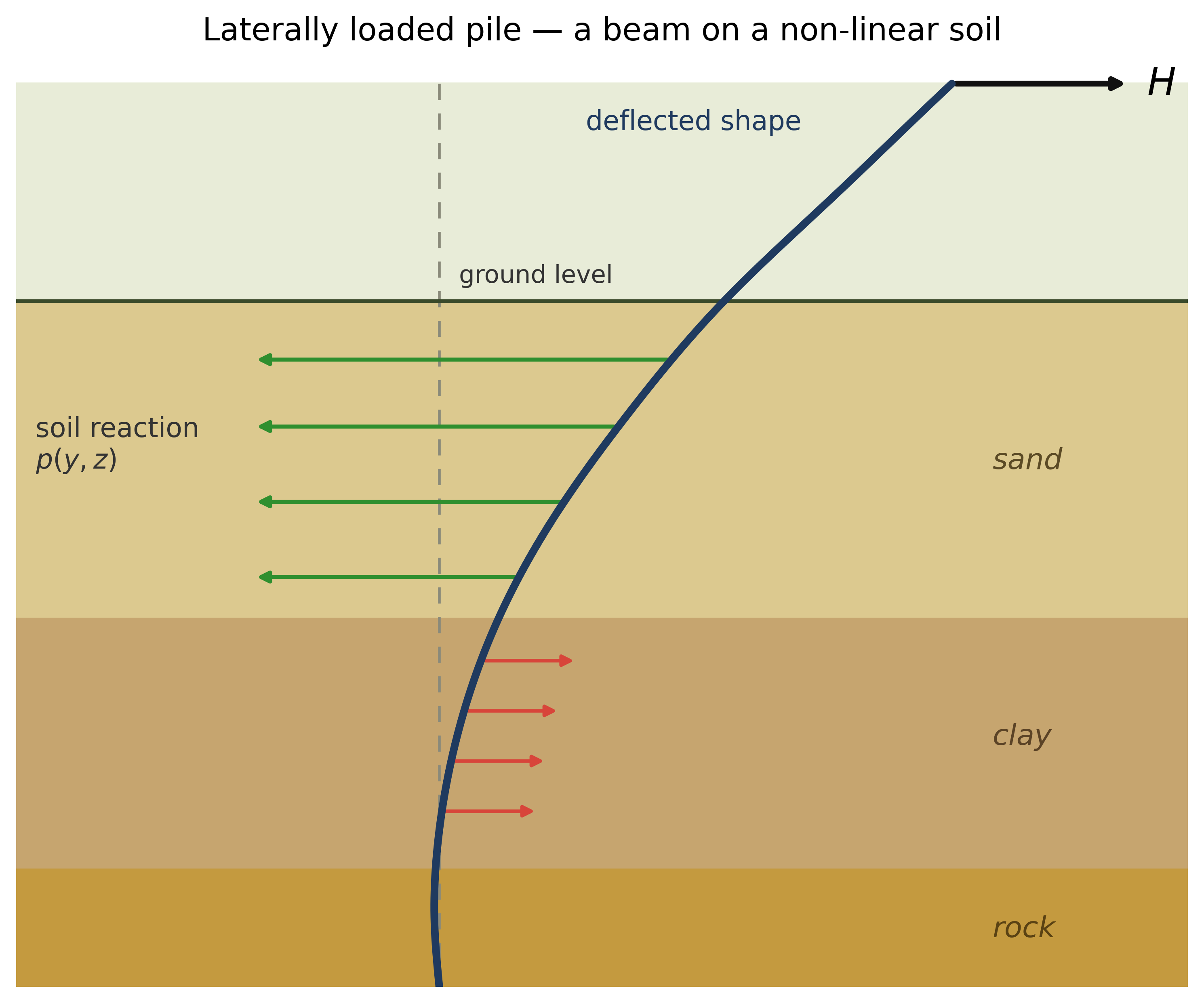
A laterally loaded pile deflects most near the surface; the soil reaction p(y,z) opposes the movement and reverses direction lower down
A laterally loaded pile deflects most near the surface; the soil reaction p(y,z) opposes the movement and reverses direction lower down, where the pile bends back the other way.

The soil resistance is neither uniform nor limitless: it grows with depth, where confining stress is higher, and softens as the soil is pushed harder. As a result, the bending moment builds up below ground, reaches a maximum a few diameters down, and then decays. Both numbers the designer needs, the head deflection and the maximum moment, fall out of this interaction, so getting the soil model right is the analysis, not a detail.

The Winkler idealisation, and where it stops

The classical approach replaces the soil with a bed of independent linear springs of constant stiffness kh, the Winkler model, for which Hetényi (1946) gives elegant closed-form solutions. greenPile still computes this and presents it as an independent baseline, because it is fast, transparent, and exact for a long pile in uniform soil at small load. But its springs never yield beyond small loads the constant-stiffness model under-predicts both deflection and moment. It is a good check, not a design basis.

The p-y method: capturing soil non-linearity

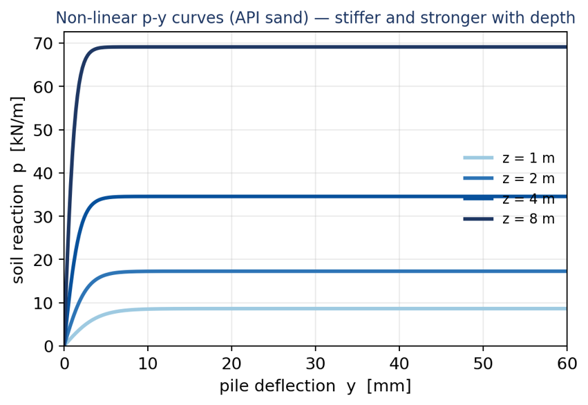
The modern design basis is the p-y method. At every depth the soil is represented not by a single spring constant but by a full non-linear curve relating the soil reaction p (force per unit length) to the local pile deflection y. Each curve is stiff and strong at depth, soft and weak near the surface, and flattens to an ultimate resistance once the soil yields. greenPile carries the established curve families (API and Reese sand, Matlock soft clay, Reese and Welch stiff clay, and Reese weak rock) and builds the appropriate curve at each node from that layer’s own strength and stiffness.

Non-linear p-y curves. The soil is stiffer and stronger with depth, and each curve flattens to an ultimate resistance once it yields
Non-linear p-y curves. The soil is stiffer and stronger with depth, and each curve flattens to an ultimate resistance once it yields.

The pile is governed by the beam-column equation, with the soil reaction entering as a non-linear, deflection-dependent term:

$$EI\frac{d^{4}y}{dz^{4}} + p(y,z) = 0$$

where the soil reaction at each point follows the secant of its p-y curve:

$$p(y,z) = k_{h}(z) \cdot D \cdot y(z)$$

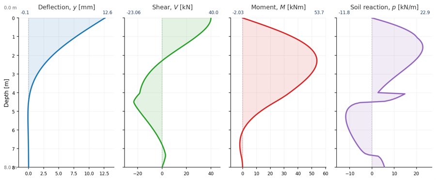
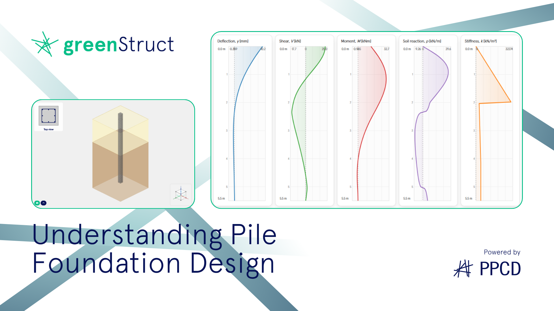
greenPile discretises the pile into elements and solves this by finite differences, iterating the soil stiffness at every node until the deflected shape and the mobilised soil resistance are in equilibrium. The outputs are the full profiles of deflection, rotation, shear, bending moment and soil reaction down the pile.

greenPile output down the pile: deflection, shear, bending moment and soil reaction
greenPile output down the pile: deflection, shear, bending moment and soil reaction. The moment builds to a maximum a few diameters below ground, and the soil reaction reverses sign with depth.

Why the method matters

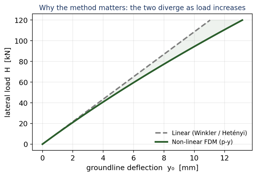
Because the near surface soil yields, the non-linear analysis always predicts a softer, larger response than the constant-stiffness idealisation, and the gap widens as the load increases. At working loads the two agree; at design loads they can differ by tens of percent. Designing off the linear result would underestimate both the deflection the structure must tolerate and the moment the pile section must carry; the linear model is unconservative exactly where it matters.

Linear and non-linear analyses coincide at small load but diverge as the load grows
Linear and non-linear analyses coincide at small load but diverge as the load grows; the non-linear p-y response is the softer, governing one.

Every load combination, not just one

A real design is not a single load case. greenPile runs the full non-linear p-y analysis for every load combination (not by scaling one reference run, which is meaningless for a non-linear problem) and reports the deflection and internal forces for each. The governing combination is then identified from the actual results, so the design is driven by the case that genuinely controls rather than the one that merely has the largest applied load.

One consistent verification: from soil to the section

Capacity and response are two of the three checks; the third is the pile section itself. greenPile carries the governing forces straight into a structural verification: the axial load, together with the bending moment and shear from the p-y analysis, is checked against the section’s M-N interaction, its shear resistance and, for concrete, its crack width, to EN 1992-1-1 for reinforced concrete or EN 1993-1-1 for steel. The section stiffness can be taken as linear (constant EI) or updated non-linearly from the cracked moment-curvature response, so the pile’s flexibility reflects its true, cracked state. The engineer sees the whole chain (soil, capacity, deflection, forces, section) in one report, for every combination.

Validation

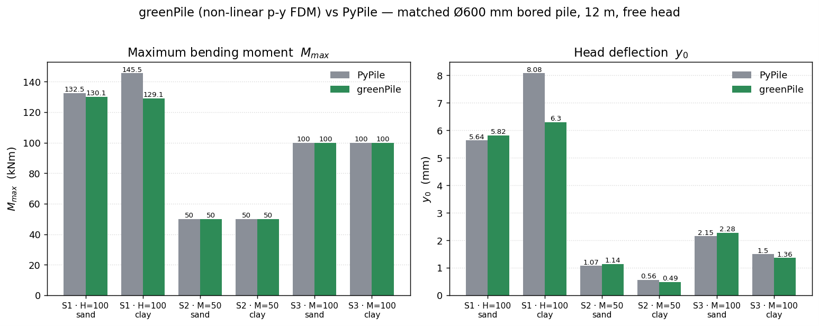
A method is only as trustworthy as its verification. greenPile’s p-y engine uses the same established p-y curve formulations as the industry standard programs such as LPILE, and its lateral response has been compared, on matched example problems, against PyPile (Yong Technology), an independent p-y program. For the same inputs the bending moments, the governing design quantity, agree closely in sand (within a few percent) and to within about ten percent in the standard clay model, where greenPile runs a little stiffer for a known reason: it carries an initial subgrade stiffness on top of the Matlock backbone, which gives slightly smaller deflections while reproducing the applied moments exactly. Larger differences appear only in a few stiff-clay and layered cases where PyPile itself becomes unstable. The axial capacity has been checked the same way: for a layered soil profile the shaft, base and total resistances computed by greenPile to EN 1997-1 reproduce an independent hand calculation to the same standard exactly. Together this supports confidence that both the lateral and the vertical engines reproduce established results.

greenPile (non-linear p-y FDM) vs PyPile on matched cases
greenPile (non-linear p-y FDM) vs PyPile on matched cases. Applied moments are reproduced exactly; sand deflections agree to within about six percent. In clay greenPile is a little stiffer.

Lateral response — greenPile (p-y FDM) vs PyPile

Load case Soil $M_{max}$ PyPile $M_{max}$ greenPile Δ $y_{0}$ PyPile $y_{0}$ greenPile Δ
H = 100 kN sand 132.5 130.1 −1.8% 5.64 5.82 +3.2%
H = 100 kN clay 145.5 129.1 −11% 8.08 6.30 −22%
M = 50 kNm sand 50.0 50.0 0% 1.07 1.14 +6.5%
M = 50 kNm clay 50.0 50.0 0% 0.56 0.49 −12%
M = 100 kNm sand 100.0 100.0 0% 2.15 2.28 +6.0%
M = 100 kNm clay 100.0 100.0 0% 1.50 1.36 −9.3%

Moment M in kNm, deflection y0 in mm. Shears also track closely. Ø600 mm bored pile, 12 m, free head; sand φ′=32°, clay cu=50 kPa (Matlock).

Axial capacity — greenPile (EN 1997-1) vs textbook hand calculation

Quantity Sand textbook Sand greenPile Δ Clay textbook Clay greenPile Δ
Shaft $R_{s,k}$ (kN) 502 501.4 0.1% 860 859.5 0.1%
Base $R_{b,k}$ (kN) 904 903.7 0.0% 178 178.1 0.0%
Total $R_{c,k}$ (kN) 1406 1405.0 0.1% 1038 1037.7 0.0%
Design $R_{c,d}$ — DA2 (kN) 1278 1277.3 0.1% 943 943.3 0.0%

Ø600 mm bored pile, 12 m embedment, water table 2 m; DA2. Agreement to within rounding (< 0.1%).

Conclusion

Designing a pile means answering two coupled questions (can it carry the load into the ground, and does it deflect, bend and remain adequate under that load), and both are governed by non-linear soil structure interaction. greenPile treats them together and to Eurocode: shaft-and-base capacity to EN 1997-1, the full non-linear p-y response for lateral action, and a code-verified section to EN 1992-1-1 / EN 1993-1-1, for every load combination and benchmarked against established software. The result is a single, transparent model of how a pile really works, so the designer can spend time on decisions rather than on bookkeeping.