Shear Reinforcement in Pad Foundations
When does concrete alone fail? Where do stirrups actually help? A complete walkthrough of one-way and two-way shear checks with all the equations you need.
When does concrete alone fail? Where do stirrups actually help? A complete walkthrough of one-way and two-way shear checks with all the equations you need.
A column pressing down on a pad foundation doesn't bend the concrete it tries to punch through it. The failure surface is a truncated cone radiating outward from the column face at roughly 26° to 45°. Unlike flexural failures that develop gradually, punching shear is sudden and brittle.
If you want the full story on how punching shear works, control perimeters, and critical section finding, see the companion article: Understanding Punching Shear in Pad Foundations.
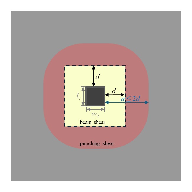
There are two distinct shear mechanisms that every pad must be checked for :
As illustrated in Figure 1, the one-way shear planes (black dashed lines) sit at a distance d from each column face, while the punching shear control perimeter (red solid) wraps around the column at 2d. Both zones are active at the same time; both checks must pass.
Punching shear is typically the governing failure mode because the loaded area (column) is small relative to the footing, creating high shear stresses on a short perimeter. This is where shear links (stirrups) become critical they can significantly increase the capacity when concrete alone isn’t enough.
Both checks must pass. If either fails or concrete alone isn’t enough, shear reinforcement (stirrups) can increase the capacity but only if they’re in the right place. That’s where most confusion starts.
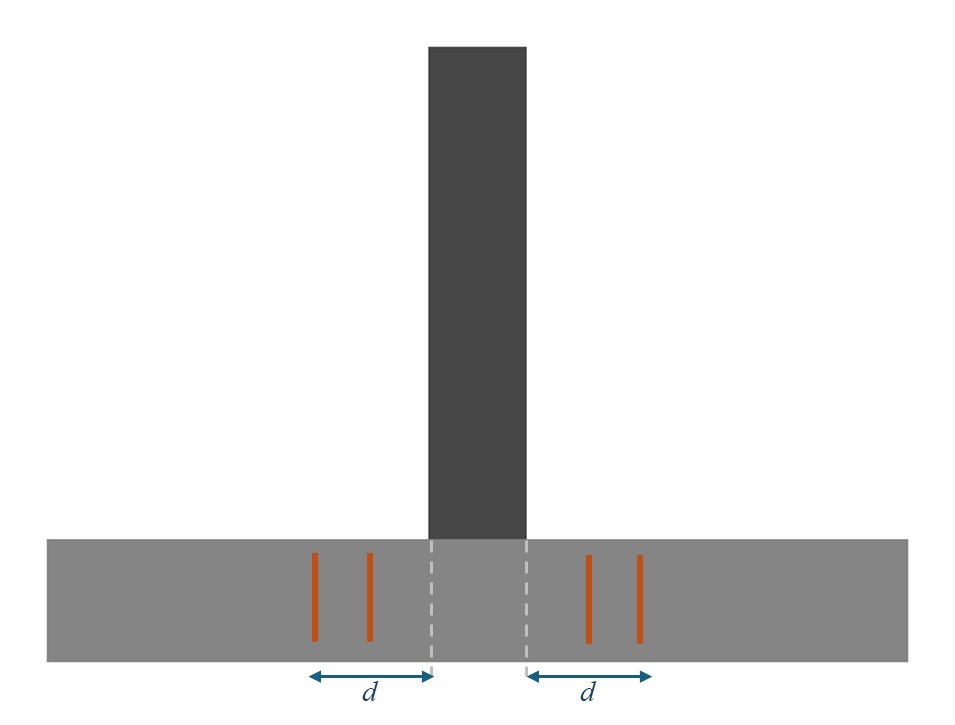
The one-way check treats the footing as a wide beam cantilevering from the column face. The critical section is at distance d from the face loads applied within d transfer directly into the column by compression and never reach the shear plane (EC2 §6.2.1(8)).
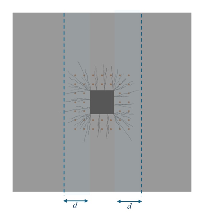
As shown in Figure 2, the critical section (dashed vertical line) sits at dd from the column face on each side. The stirrups shown in orange cross this section, which is exactly what makes them effective.
The concrete alone must resist the applied shear force at the critical section (EN 1992-1-1 §6.2.2 Eq. (6.2.a)):
$C_{Rd,c} = \frac{0.18}{\gamma_c}$
$k = 1 + \sqrt{\frac{200}{d}} \leq 2.0 \quad \text{(size effect factor, } d \text{ in mm)}$
$\rho_l = \min\left(\sqrt{\rho_{lx} \cdot \rho_{ly}},\,0.02\right) \quad \text{(geometric mean of reinforcement ratios)}$
A common question: if we place stirrups around the edges of the pad (peripheral stirrups), will they help with beam shear?
Look at Figure 3. The peripheral stirrups (black dots) are placed along all four edges of the pad. The one-way shear critical section (blue dashed line) is at a distance d from the column face deep inside the pad. The peripheral stirrups sit far beyond that section and never cross it. Unless the stirrups actually cross this section, they contribute nothing to beam shear resistance.
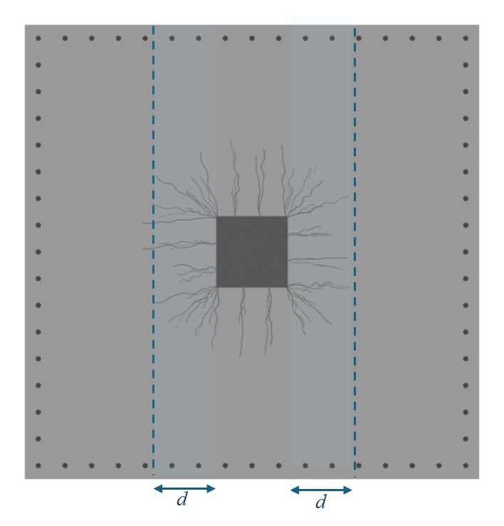
They also don’t help punching shear. Punching shear links must be within 2d of the column face. Peripheral stirrups are typically well beyond this zone.
So if peripheral stirrups don’t help, what does?
Grid stirrups placed around the column do cross the one-way shear critical section at a distance d from the face.
As shown in Figure 4, the stirrup legs (dotted pattern) extend to the critical section (blue dashed line) and cross it, providing the direct shear resistance that peripheral stirrups cannot. When beam shear fails the concrete-alone check, these stirrups provide the additional capacity needed.
When a diagonal shear crack forms, each stirrup leg crossing the crack develops a tensile force. The concrete carries compression (struts), the stirrups carry tension (ties) forming a truss mechanism.
When $V_{Ed} > V_{Rd,c}$ the required stirrup reinforcement is (EN 1992-1-1 §6.2.3, derived from Eq. (6.8)):
$A_{sw}$: total area of stirrup legs per section cut
$s$: spacing of stirrups along the beam direction
$z$: lever arm, typically $0.9d$
$f_{ywd}$: design yield strength of stirrups $= f_{ywk} / \gamma_s$
$\cot \theta$: strut angle, EC2 permits values between $1.0$ and $2.5$
Punching shear is the more critical failure mode for most pad foundations. The column tries to punch through the concrete along a truncated cone. The failure is sudden and brittle there’s no warning.
The 3D view in Figure 5 shows how the failure cone radiates outward from the column base. The red shaded area on the pad surface marks the punching zone notice how it extends well beyond the column footprint in every direction.

Before you design a single stirrup, Eurocode 2 requires you to understand where and how the shear capacity is checked.
As shown in Figure 6, there are three concentric zones around the column, each with its own verification. The red inner zone covers $u_0$ and $u_1$, where strut crushing, and stirrup capacity are checked. The green outer zone ($u_{\text{out}}$) is where concrete alone takes over.
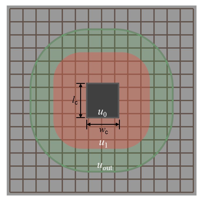
| Zone | Perimeter | Distance | Check | What it means |
|---|---|---|---|---|
| 1 (red) | $u_0$ | Column face | $v_{Ed} \le v_{Rd,max}$ | Strut crushing; if it fails, change geometry |
| 2 (red) | $u_1$ | 0 to $2d$ | $v_{Ed} \le v_{Rd,cs}$ | Where stirrups work |
| 3 (green) | $u_{out}$ | Beyond links | $v_{Ed} \le v_{Rd,c}$ | Concrete alone is enough; links can stop here |
The critical insight: stirrups can only help in zone 2. If the strut crushing check at the column face fails, no amount of reinforcement will save you; you need a bigger column or a thicker pad. And beyond the outer perimeter, the concrete handles things on its own.
The concrete compression struts at the column face must not crush:
Maximum shear stress capacity(EN 1992-1-1 §6.4.5(3))
$\nu = 0.6 \left( 1 - \frac{f_{ck}}{250} \right) \quad \text{(strength reduction factor for cracked concrete)}$
$f_{cd} = \frac{\alpha_{cc} \cdot f_{ck}}{\gamma_c}$
The applied shear stress at the column face ($𝑢_0$)
If $v_{Ed} > v_{Rd,max}$, the section is too small. Full stop. Increase the footing depth or column size.
This is where stirrups earn their keep. The concrete shear capacity at the control perimeter, enhanced for foundations (EN 1992-1-1 §6.4.4(2) with enhancement factor):
$C_{Rd,c} = 0.18/\gamma_c$
$k = 1 + \sqrt{200/d} \le 2.0$ (size effect factor,d in mm)
$\rho_l = \min(\sqrt{\rho_{lx} \cdot \rho_{ly}}, 0.02)$ (geometric mean of reinforcement ratios)
$v_{min} = 0.035k^{3/2} f_{ck}^{1/2}$
$2d/a$ =Enhancement factor (only when a<2d)
When concrete alone isn’t enough, add stirrups. The combined capacity (EN 1992-1-1 §6.4.5) :
The 0.75 factor acknowledges that cracked concrete provides less than its full capacity. The effective yield strength of punching shear links is capped by EC2 (EN 1992-1-1 §6.4.5(1)):
Beyond the last row of stirrups, concrete must handle the remaining stress on its own. The outer perimeter $u_{out}$ is where $v_{Ed}$ finally drops below $v_{Rd,c}$ (without the enhancement factor). Beyond this no further links needed.
Effectiveness cap. EC2 limits the reinforced capacity to $k_{max} \times v_{Rd,c}$ (typically 1.5). Even with heavy shear reinforcement, capacity is capped. Beyond this ceiling, only thicker concrete or a larger column will help.
Shear links don't go everywhere in the pad. They occupy a precisely defined annular zone around the column. As shown in the elevation view of Figure 7, the first row sits close to the column face, and successive rows fan outward with controlled radial spacing all within the 2d outer limit.

The number of perimeters follows directly: $n=(2d-0.3d)/s_r+1$, typically giving 3–5 rows of links for common pad dimensions.
| Rule | Requirement | EC2 Clause |
|---|---|---|
| First perimeter distance | $\le 0.3d - 0.5d$ from column face | §9.4.3(1) |
| Radial spacing ($s_r$) | $\le 0.75d$ | §9.4.3(1) |
| Tangential spacing ($s_t$) | $\le 1.5d$ (inner), $\le 2.0d$ (outer) | §9.4.3(1) |
| Outer limit | $\le 2d$ from column face | §6.4.5 |
The column’s position on the pad determines how much of the control perimeter is available. Less perimeter means less concrete resisting shear, which means higher stress and greater demand on stirrups.
The control perimeter wraps completely around the column. This is the most favourable case. As seen in Figure 8, the full red zone is available on all four sides the stirrups (dotted grid) fan out symmetrically around the column with no truncation.
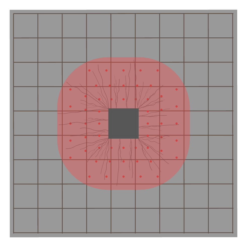
The full perimeter is available
The perimeter is truncated on one side. Stirrups are placed on three sides
With β = 1.0 for concentric loading, the full perimeter provides maximum resistance. When moments are present, β increases to account for non-uniform shear distribution (EN 1992-1-1 §6.4.3):
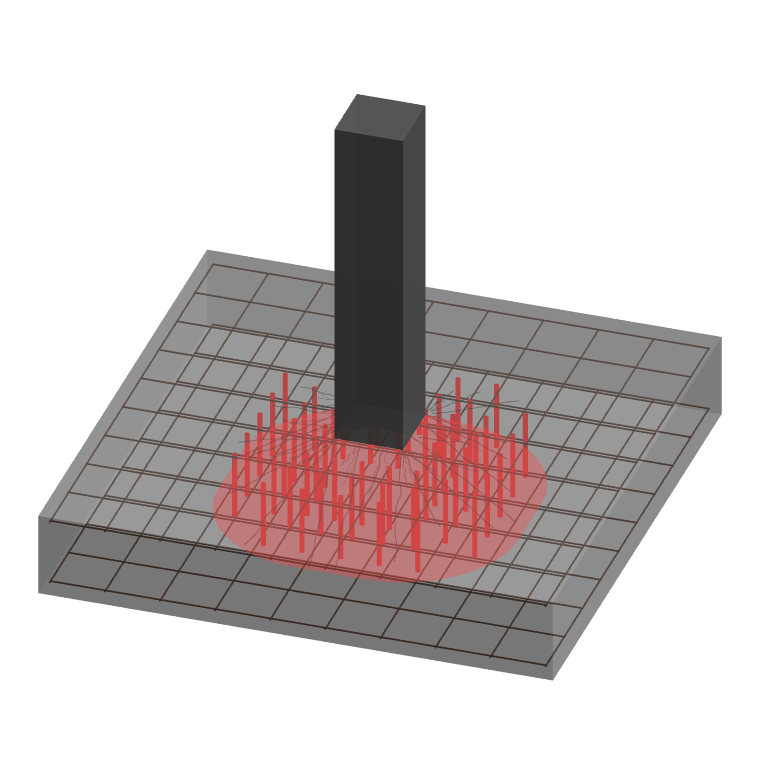
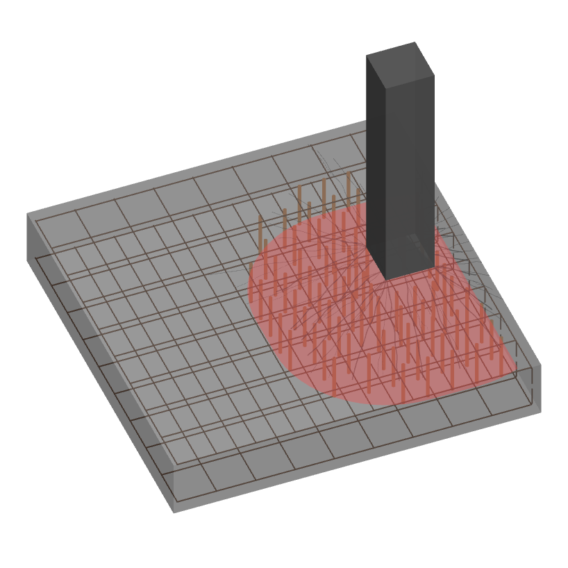
One side of the control perimeter is truncated at the footing boundary. The perimeter shortens and the eccentricity factor increases to β = 1.4. In Figure 9 you can see how the red punching zone is cut off on the right side only three sides of the column have perimeter available, and the stirrups are concentrated accordingly.

The direction of the moment also matters. A moment pushing the resultant toward the free edge is more severe than one pushing toward the supported side. This directional check can make the difference between requiring links or not.
Two sides are lost to the pad edges. Only a quarter-circle arc remains on the free quadrant. The β factor rises to 1.5 and the available perimeter drops significantly. As shown in Figure 10, the red zone is reduced to just the free quadrant the stirrups occupy only that corner area.
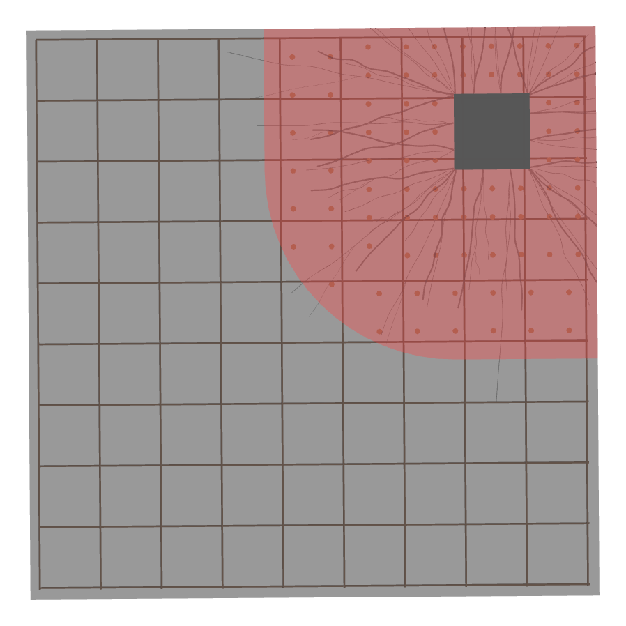
Only the free quadrant has perimeter available
| Position | Perimeter | $\beta$ Factor | Stirrup cage | Typical demand |
|---|---|---|---|---|
| Internal | Full (4-sided) | 1.0 (axial) | 4-sided | Often sufficient without links |
| Edge | 3-sided | 1.4 | 3-sided | Higher demand, links may be required |
| Corner | Quarter only | 1.5 | Free quadrant | Most demanding, links frequently required |
As you lose perimeter, you lose capacity. A corner column can require two to three times the shear link area of an identically loaded internal column. Figure 11 puts all three cases side by side in 3D, the progressive clipping of the failure cone by the pad edges is immediately visible.

All of this one-way shear, punching shear, column position, stirrup placement is handled automatically by greenPad.
Unlike elevated slabs where the critical section is fixed at 2d, pad foundations require searching for the worst-case perimeter (EC2 §6.4.4). greenPad performs this iterative sweep automatically. For a detailed explanation of how the critical perimeter is found, see our Understanding Punching Shear in Pad Foundations.
The soil reaction inside the control perimeter acts upward, directly reducing the net punching force:
For large pads this can account for 20–40% of the applied load. greenPad calculates this deduction at every perimeter distance automatically.
When either beam shear or punching shear exceeds the concrete capacity, greenPad:
The grid stirrup layout is preferred because it simultaneously serves both beam shear (legs crossing the critical section at d) and punching shear (legs within the 2d zone around the column). Peripheral stirrups are reported separately, with a clear indication of whether they contribute to the governing check.
All of these checks, one-way shear, punching shear, iterative critical section search, soil deduction, column position, stirrup contribution, are performed automatically for every load case. greenPad finds the governing failure mode, reports the utilisation, and tells you exactly how much reinforcement you need. No manual iteration, no missed checks